Background Information


Some Technical Details

The gears in the mechanism

The gearwheels are referenced by the shaft they are mounted on.

shaft 0 1 2 3 4 5 6 remarks
A   20           drive shaft for simulation
B_0_1_2 20 20 64         Year
B_3       32       Moon
C   38 48          
D   24 127          
E_1_6   32         50  
E_2_5     32     50    
E_3_4       223 188      
F   53 30          
G   54 20         Saros
H   60 15          
I   60           Exeligmos
L   38 53          
M   96 15 27        
N   53 15         Metonic
P   60 12          
O   60           Callippic
Q 20              
K   50 50         Moon Phase Sphere

total drive train

---> A1 x B1 -------------------------------------------------------------------------------> Year
          =
          =
          B2 x L1             P2 x O1 ------------------------------------------------------> Callippic   
          =    L2 x M1   N2 x P1
          =         M2 x N1 ----------------------------------------------------------------> Metonic x 5
          =         =
          =         M3 x E3
          =              E4 x F1
          =               |   F2 x G1 ------------------------------------------------------> Saros x 4
          =               |        G2 x H1
          =               |             H2 x I1 --------------------------------------------> Exeligmos
          =               |        
          =               |             a)
          =               |          +------+     b)
          =                --------> |b     |  +------+    
          B2 x C1                    |      |  | pin  |
          =    C2 x D1               |   a-b|--| and  |-- K2 x E6
          =         D2 x E2          |      |  | slot |        E1 x B3 ---------------------> Moon
          =              E5 x K1 --> |a     |  +------+                  |
          =                          +------+                            |       c)
          =                                                              |    +------+
          =                                                               --> |a     |
          =                                                                   |      |
          =                                                                   |   a-b|------> Lunar Phase    
          =                                                                   |      |        Sphere
          B0 x Q1 ----------------------------------------------------------> |b     |   
                                                                              +------+
legend
F1
F2
Wheels F1 and F2 are mounted on the same shaft

M2
=
M3
Wheels M2 and M3 are mounted on the same shaft

M3 x E3
Wheel M3 drives wheel E3

I1 ---> Exeligmos
Wheel I1 drives the Exeligmos pointer
The Exeligmos pointer is mounted on shaft I
notes:
a)
Wheels K1 and K2 are mounted on E3 and E4.
Subtract the (slower) rotation of E3+E4 from the faster rotation of K1.

b)
The pin-and-slot mechanism that varies the rotation of the moon pointer and the lunar phase sphere.

c)
The bevel gear to drive the lunar phase sphere is mounted on top of the slower rotating year pointer.
Subtract it from the rotation of the moon pointer.

the pin and slot mechanism

The transfer function of the pin and slot mechanism is:

out_ang = atan2 ( r_pin * sin ( in_ang ), r_pin * cos ( in_ang ) - exen )

in_ang
the angle of wheel K1 (the input)
out_ang
the angle of wheel K1 (the output)
excen
exentricity of the shafts of K1 and K2
r_pin
distance between the center of wheel K1 and the center of the pin

Total Speed Reduction

pointer value VRML
axes
remarks
Year -1.000000 Z driven trough 1:1 bevel gear from simulator
Saros x 4 0.221855 Z  
Exeligmos 0.018488 Z  
Metonic x 5 0.263158 Z  
Callippic 0.013158 Z  
Moon -13.368421 Z Non linear due to pin-and-slot mechanism
Lunar Phase Sphere 12.368421 Y Non linear due to pin-and-slot mechanism

VRML Coordinate System

The VRML coordinate system is righthanded.

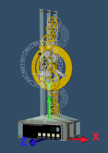
Most rotations are along the displaced z-axes.

Axes of the Antikythera model